
Selecting the right thermal management component for any engine or transmission system is rarely a straightforward decision. When it comes to oil coolers, engineers and procurement specialists often face a wide range of performance specifications that can seem confusing at first glance. Understanding which cooling capacity metrics actually drive the selection process is essential for avoiding costly mismatches between the cooler's capabilities and the demands of the application.
Not all oil coolers are built for the same duty cycle, flow environment, or heat rejection requirement. A component that performs flawlessly in a light-duty automotive application may fall critically short in a high-cycle industrial gearbox or a performance racing engine. This article breaks down the key cooling capacity metrics that matter most during the selection process, explains what each one means in practical terms, and shows how they interact to define overall thermal performance. Whether you are specifying oil coolers for engine lubrication, hydraulic circuits, or transmission systems, the following framework will help you make a well-informed decision.
Understanding Heat Rejection Rate as the Primary Metric
Why Heat Rejection Rate Defines Thermal Performance
Heat rejection rate, typically expressed in kilowatts (kW) or British Thermal Units per hour (BTU/hr), is the foundational metric for evaluating oil coolers. It represents the total amount of thermal energy that the cooler can transfer from the oil to the surrounding coolant medium — whether that is ambient air or a liquid cooling circuit — within a defined time period. Without understanding the heat rejection rate required by your system, every other specification becomes secondary and potentially misleading.
To calculate the required heat rejection rate, engineers typically assess the power losses within the system being cooled. In an engine, this includes friction losses across bearings, pistons, and valve trains. In a hydraulic system, it includes pump inefficiencies and pressure drop losses. The oil temperature rise that results from these losses, combined with the target oil temperature range, directly determines the minimum heat rejection rate that the selected oil coolers must deliver.
It is important to match the rated heat rejection capacity of oil coolers to the worst-case thermal load rather than average operating conditions. Undersizing the cooler based on average load leaves the system vulnerable during peak demand phases, leading to accelerated oil degradation and potential component failure. Experienced engineers typically add a safety margin of 15 to 25 percent above the calculated peak heat load when finalizing their specifications.
How Operating Temperature Differential Affects Heat Rejection
Heat rejection rate is not a fixed absolute figure — it is directly tied to the temperature differential between the oil entering the cooler and the cooling medium receiving that heat. This relationship is commonly expressed as the Log Mean Temperature Difference (LMTD) in heat exchanger engineering. The greater the temperature differential, the more heat the cooler can reject for a given surface area and flow rate.
This means that oil coolers specified for high ambient temperature environments — such as desert industrial sites or enclosed machinery rooms — must have higher thermal capacity ratings than those used in temperate climates, even if the heat load generated by the machinery is identical. When reviewing manufacturer performance data for oil coolers, always verify the ambient and inlet oil temperatures assumed in the test conditions, as these figures significantly affect comparability between different products.
A practical implication of LMTD sensitivity is that oil coolers which perform adequately during winter commissioning may reveal inadequate capacity during summer peak conditions. Procurement teams should request performance curves across a range of temperature differentials rather than relying on a single rated point, ensuring that the selected unit will maintain acceptable oil temperatures throughout the full operational year.
Oil Flow Rate and Pressure Drop Considerations
Matching Flow Rate Capacity to System Requirements
Oil flow rate, measured in liters per minute (L/min) or gallons per minute (GPM), is the second most critical metric when evaluating oil coolers. The cooler must be capable of handling the full flow delivered by the oil pump without creating excessive restriction. If the cooler's internal channels are too narrow or too long relative to the system's pump output, back pressure builds up and can reduce lubrication effectiveness or trigger bypass valve operation.
Oil coolers are rated for a maximum flow rate at which they can operate without exceeding acceptable pressure drop limits. This rating is directly related to the internal passage geometry, the number of rows or plates within the core, and the viscosity of the oil at operating temperature. High-viscosity oils — common in cold-start conditions or in certain industrial gear oils — demand more generous flow passage sizing than lighter engine oils running at full operating temperature.
When selecting oil coolers for systems with variable flow pumps or wide viscosity ranges, it is advisable to evaluate the pressure-flow curve across multiple operating points rather than checking a single maximum flow figure. This ensures that the cooler remains within its designed operating envelope during all phases of machine operation, including cold starts, warm-up cycles, and peak load conditions.
The Role of Pressure Drop in System Efficiency
Pressure drop across oil coolers directly affects the energy consumption of the lubrication circuit. Every bar of pressure drop that the cooler introduces means the pump must work harder to maintain adequate oil pressure and flow to critical components. In systems where energy efficiency is a key design criterion — such as in mobile machinery or energy-intensive industrial processes — minimizing cooler-induced pressure drop is an important optimization target alongside thermal performance.
The relationship between pressure drop and flow rate is roughly quadratic: doubling the flow rate roughly quadruples the pressure drop through a fixed-geometry cooler. This nonlinear relationship is why oil coolers sized generously for flow rate tend to have disproportionately lower pressure drop penalties at normal operating flows, providing a useful efficiency buffer when flow rates temporarily spike during demanding operating cycles.
Engineers selecting oil coolers for turbocharged engines or high-performance transmission systems should pay particular attention to pressure drop specifications at both hot and cold oil conditions. Cold oil is significantly more viscous and can generate pressure drops several times higher than warm oil at the same volumetric flow rate, making cold-start pressure management a genuine design concern rather than a theoretical edge case.
Core Size, Row Count, and Surface Area
How Physical Size Translates to Cooling Capacity
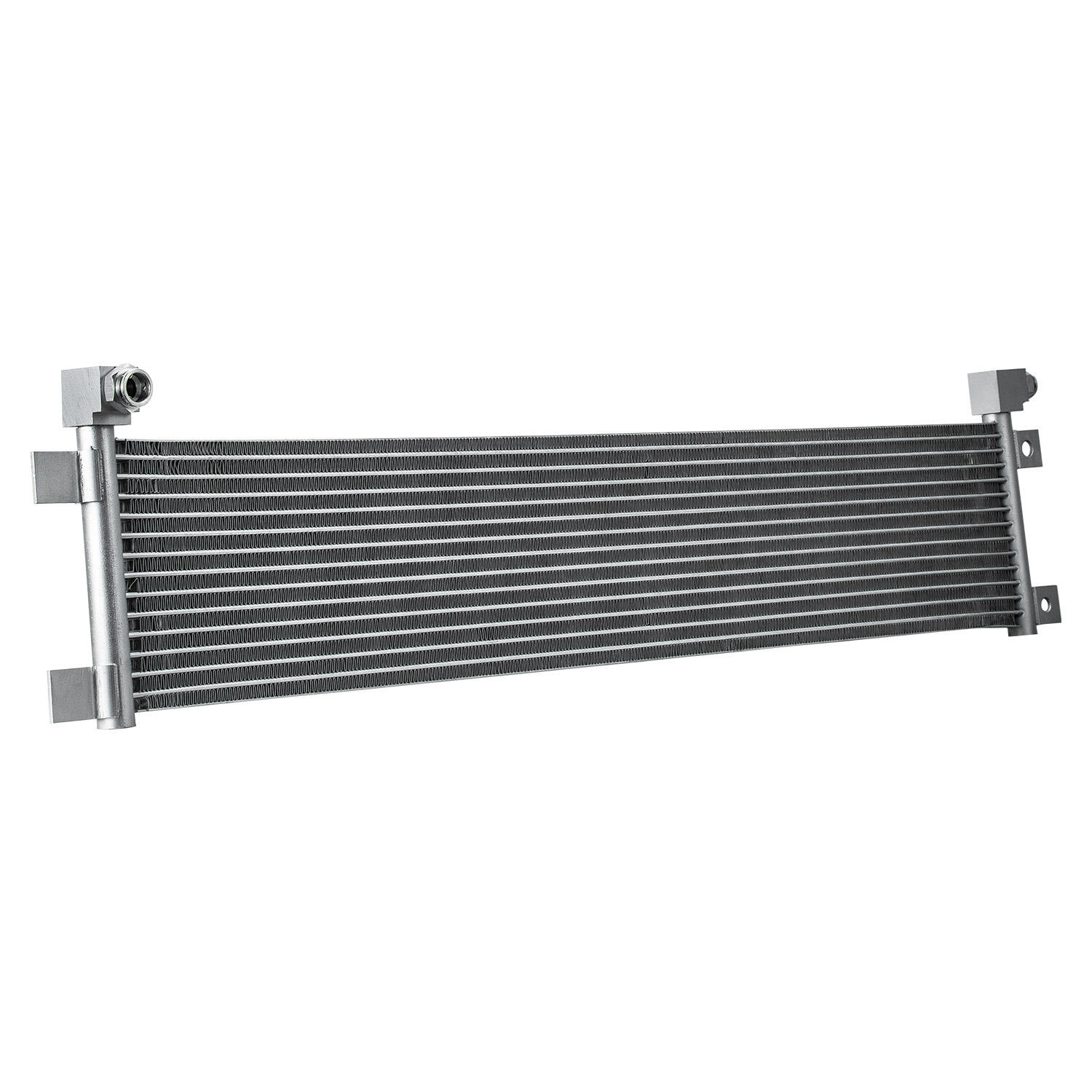
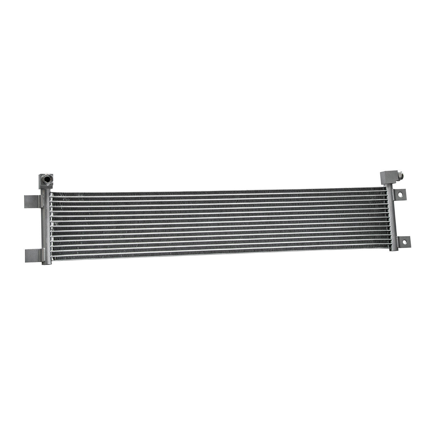
The physical dimensions of oil coolers — particularly the number of cooling rows, the core height and width, and the fin density — directly determine the available heat transfer surface area. Greater surface area generally enables higher heat rejection at a given flow rate and temperature differential, which is why multi-row oil coolers are favored for high-performance and heavy-duty applications. A 15-row aluminium oil cooler, for example, offers substantially more surface area than a 7-row unit of similar external width, translating directly into greater thermal capacity.
However, larger physical dimensions also mean greater weight, higher material cost, and more complex installation requirements. Packaging constraints in automotive and mobile machinery applications often limit how large the oil cooler can physically be, forcing engineers to prioritize among competing design objectives. Understanding the relationship between row count, core depth, and heat rejection rate helps in making rational trade-offs when perfect solutions are unavailable.
Fin density, expressed in fins per inch (FPI), is another physical parameter that influences both heat transfer and pressure drop. Higher fin density increases surface area but also increases airflow resistance in air-cooled oil coolers, potentially reducing the airflow that drives heat rejection. The optimal fin density depends on the available cooling airflow velocity, the required heat rejection rate, and the acceptable pressure drop limit for the air side of the circuit.
Material Selection and Its Impact on Thermal Metrics
The thermal conductivity of the core material affects how efficiently heat moves from the oil passages into the fin structure and ultimately into the cooling medium. Aluminium is the most widely used material for oil coolers in automotive, motorsport, and light industrial applications because it offers an excellent combination of thermal conductivity, low weight, corrosion resistance, and manufacturability. The high conductivity of aluminium ensures that even thin-walled passages and fins remain thermally efficient.
In heavier industrial applications, copper-brass construction has historically been used because of its even higher thermal conductivity and robust mechanical properties. However, aluminium oil coolers have largely replaced brass units in most modern applications due to weight advantages, improved alloy performance, and better compatibility with modern coolant chemistries. When reviewing specifications, verifying the core material is important for understanding the thermal efficiency per unit weight and the long-term durability of the component.
Weld quality and core construction integrity also affect real-world thermal performance. A well-brazed aluminium core maintains consistent internal passage geometry and eliminates hot spots or flow bypass paths that would reduce effective heat transfer. Procurement specifications for oil coolers should include core construction standards and pressure test requirements to ensure that physical integrity supports the rated thermal performance throughout the component's service life.
Fitting Size, Port Configuration, and Integration Metrics
The Importance of Port Size and Connection Standard
Oil coolers must integrate seamlessly with the existing oil circuit, and port size is a direct determinant of whether the cooler can physically handle the required flow without creating a restriction. AN-10 fittings, for example, are a common standard in performance automotive and motorsport applications, providing a balance between flow capacity and installation practicality. Matching the port size of the cooler to the internal diameter of the oil lines eliminates avoidable pressure drop caused by transitions between different bore sizes.
Mismatched port sizes between oil coolers and the connected pipework can create turbulence, localized pressure losses, and even erosion of fittings over time in high-cycle applications. When specifying oil coolers for a new installation, it is best practice to standardize on a fitting size that matches the oil system's pump outlet and main supply line diameter, rather than adapting incompatible standards together with reducers or expanders.
Port orientation — whether the inlet and outlet are on the same side, opposite ends, or at specific angular positions — also affects how easily oil coolers can be packaged within constrained installation spaces. Universal-mount oil coolers with flexible port configurations offer significant installation versatility, particularly when retrofitting cooling capacity into existing systems where the original design did not anticipate the thermal load that has since developed.
Thermostat and Bypass Integration Considerations
Many oil coolers are specified in conjunction with thermostatic bypass valves that regulate oil temperature by diverting oil away from the cooler during cold-start conditions. The thermostat's opening temperature and full-flow temperature range must be considered alongside the cooler's thermal capacity to ensure that the combined system achieves target oil temperature within an acceptable warm-up time while preventing overtemperature during sustained high-load operation.
When evaluating oil coolers for thermostated circuits, the cooler's pressure drop at maximum flow must be compatible with the bypass valve's differential pressure characteristics. A cooler with very high pressure drop may cause excessive bypass valve opening even at normal operating temperatures, effectively reducing the oil flow through the cooler and compromising thermal control. Reviewing cooler and thermostat specifications together — rather than independently — avoids these integration pitfalls.
For high-performance engine and transmission oil coolers, some installations benefit from sandwich-plate adapter systems that integrate the thermostat, pressure relief valve, and cooler inlet/outlet in a single assembly. These integrated configurations simplify installation, reduce the number of potential leak points, and ensure precise thermal regulation from a system-level perspective. When specifying oil coolers for such configurations, confirming compatibility with available adapter standards is a necessary part of the selection process.
FAQ
What is the most important cooling capacity metric when selecting oil coolers?
Heat rejection rate is the primary metric because it directly determines whether the cooler can manage the thermal load generated by the system being cooled. All other metrics — flow rate, pressure drop, and surface area — support and constrain the achievable heat rejection rate. Always calculate your required heat rejection rate first before evaluating any other specification of oil coolers.
How does ambient temperature affect oil cooler selection?
Ambient temperature directly affects the temperature differential between the oil and the cooling medium, which drives the rate of heat transfer. Oil coolers installed in high ambient temperature environments must be rated for greater heat rejection capacity than identical systems operating in cooler climates, even when the machinery generates the same heat load. Always specify oil coolers using worst-case ambient temperature conditions to ensure reliable thermal control year-round.
Does row count always indicate better performance in oil coolers?
Higher row counts generally provide greater heat transfer surface area, which supports higher heat rejection capacity, but they also increase core depth, weight, and pressure drop. The optimal row count for oil coolers depends on the balance between available installation space, acceptable pressure drop, required heat rejection rate, and airflow availability. More rows are not always better — they must be matched to the specific thermal and flow requirements of the application.
What fitting size is recommended for high-performance oil coolers?
AN-10 fittings are widely used for high-performance and motorsport oil coolers because they offer sufficient flow area for most performance engine applications while remaining practical to install. The correct fitting size should always match the internal diameter of the oil system's supply and return lines to avoid creating additional pressure losses at connection points. Consult the oil system's flow rate requirements and compare them against fitting flow capacity data when finalizing the specification for oil coolers.