
For OEM buyers sourcing components for engine cooling systems, the specification process for an overflow tank is far more structured and technically demanding than a simple parts lookup. Unlike aftermarket procurement, OEM specification requires a precise alignment between the overflow tank design and the broader thermal management architecture of the engine system it serves. Every dimensional, material, and performance parameter must be locked in before a component can enter a validated bill of materials.
Understanding how OEM engineering and procurement teams approach overflow tank specification reveals the depth of technical coordination involved. From capacity calculations to pressure thresholds, mounting geometry to material compatibility, each decision directly affects system reliability, warranty performance, and long-term cost of ownership. This article walks through the complete specification logic that experienced OEM buyers apply when defining requirements for an overflow tank in engine cooling applications.
The Functional Role of an Overflow Tank in Engine Cooling Systems
Pressure Management and Coolant Recovery
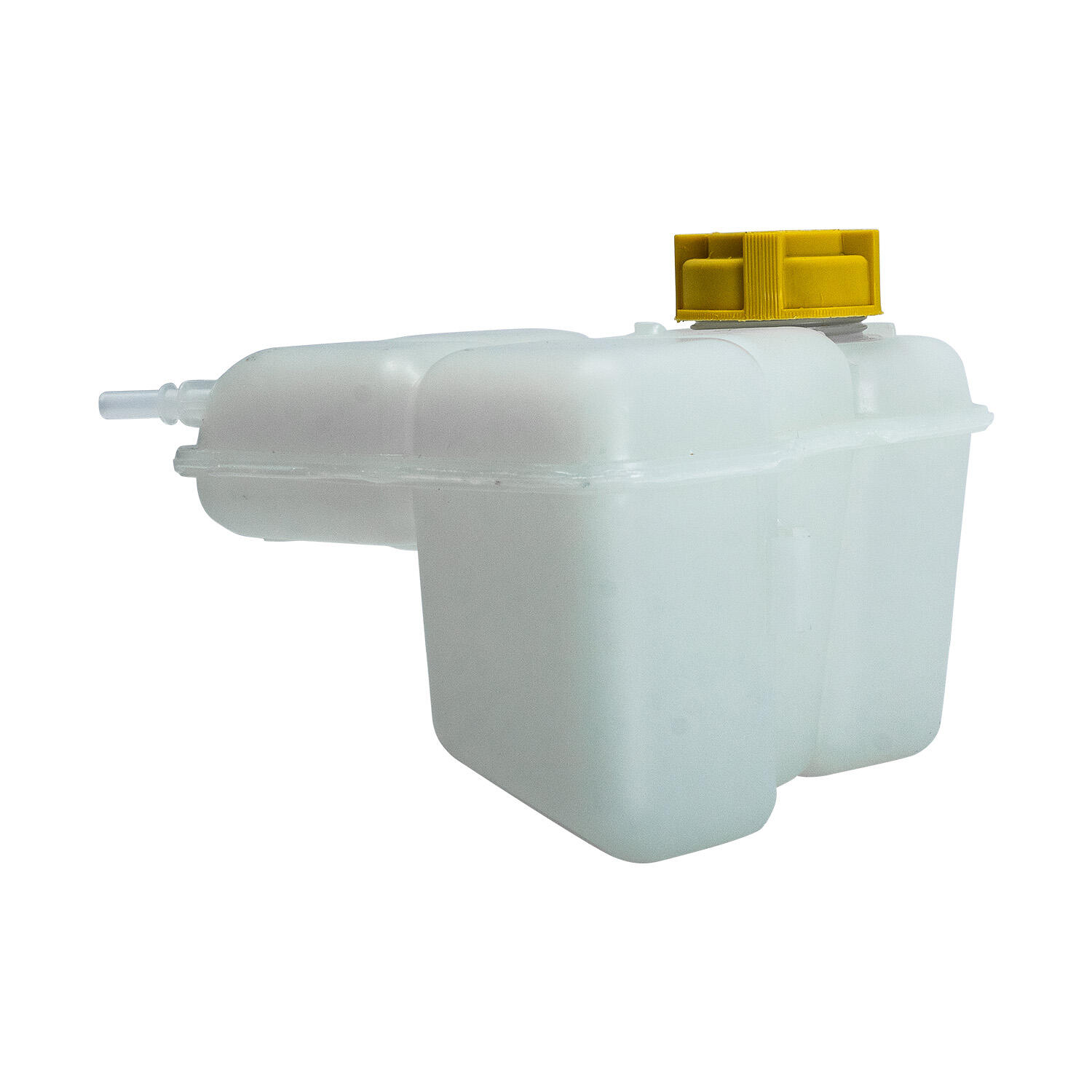
An overflow tank serves as a controlled expansion chamber within the engine cooling circuit. As coolant heats up during engine operation, it expands and requires somewhere to go that does not result in pressure loss or fluid waste. The overflow tank captures this excess volume during high-temperature cycles and returns it to the radiator once the system cools down, maintaining the correct coolant level at all times.
This recovery function is critical to long-term engine health. Without a properly specified overflow tank, cooling systems lose fluid gradually through thermal cycling, which leads to air pockets in the circuit, reduced heat transfer efficiency, and eventual overheating risk. OEM buyers understand that the overflow tank is not a passive reservoir but an active participant in pressure regulation.
The operating pressure range of the overflow tank must be matched to the radiator cap rating and the system's peak operating temperature. Mismatches in these values result in premature cap venting, coolant loss, or insufficient recovery volume, all of which compromise system performance and increase warranty claims.
Venting Logic and System Integration
Beyond fluid recovery, the overflow tank also functions as the primary venting point for air purging during system fill and operation. Many OEM engine systems are designed so that air naturally migrates toward the overflow tank, where it can be released without entering the main cooling circuit. This makes the placement, inlet geometry, and vent port design of the overflow tank critical to how quickly a system bleeds air after service or initial fill.
OEM engineers typically define the vent port location and hose routing as part of the cooling system layout early in the vehicle or equipment design phase. The overflow tank specification must align with these routing constraints, meaning the supplier must understand not just the tank in isolation but how it fits within the complete thermal management architecture.
Key Technical Parameters OEM Buyers Define During Specification
Volumetric Capacity and Reserve Margin
The most fundamental parameter in overflow tank specification is volumetric capacity. OEM buyers calculate the required expansion volume based on the total coolant charge in the system, the expected temperature rise from cold start to peak operating temperature, and the thermal expansion coefficient of the coolant formulation being used. A typical specification includes both a minimum working capacity and a total tank volume that provides a safe reserve margin above the maximum expansion volume.
Under-specifying capacity is a common source of field failures. If the overflow tank fills completely during a heat cycle, the excess pressure has nowhere to go except through the pressure cap, resulting in coolant loss and potential overheating. OEM buyers typically add a buffer of fifteen to twenty-five percent above the calculated expansion volume to account for worst-case ambient conditions, degraded coolant, and aging system components.
For engines with large coolant volumes, such as those used in commercial vehicles, heavy equipment, or high-displacement performance applications, the overflow tank capacity requirement can be substantially larger than a comparable passenger vehicle application. Buyers must ensure the specified overflow tank is scaled correctly for the engine class being served.
Operating Pressure Rating and Cap Specification
Every overflow tank specification must include a clearly defined operating pressure rating that matches the system's radiator cap pressure setting. Common pressure cap ratings range from 0.9 bar to 1.4 bar for most passenger and light commercial applications, while heavy-duty engine systems may operate at higher pressures. The overflow tank body must be structurally capable of sustaining continuous cyclic pressure loading at the specified rating without deformation, cracking, or seal degradation.
OEM buyers often require pressure cycle testing as a validation requirement, specifying a minimum number of pressure cycles between defined limits before any material fatigue or dimensional change is acceptable. This requirement directly informs the wall thickness, geometry, and material selection of the overflow tank. A tank that passes static pressure hold testing but fails cyclic fatigue testing is not acceptable in an OEM context.
The cap seat design and sealing surface on the overflow tank must also be specified to ensure long-term sealing integrity. OEM buyers will often define the cap interface dimensions, torque requirements, and seal material compatibility as part of the overflow tank drawing package rather than leaving these details to the supplier.
Material Selection and Coolant Compatibility
Material selection for an overflow tank is driven by three overlapping requirements: chemical compatibility with the coolant formulation, thermal resistance across the full operating temperature range, and structural durability under the vibration and pressure cycling experienced in service. OEM buyers must specify the material in precise terms rather than leaving it as an open choice for the supplier.
Plastic overflow tanks are commonly used in passenger vehicle applications where weight, cost, and ease of molding are priorities. However, the specific resin must be validated against the coolant chemistry. Many modern OAT and HOAT coolant formulations can attack certain nylon or polypropylene grades if the resin is not properly stabilized. OEM buyers typically specify the resin grade by material designation and require chemical compatibility test results as part of the supplier approval package.
Aluminum overflow tanks offer advantages in high-temperature, high-pressure, or high-vibration applications where the structural properties of plastic are insufficient. An aluminum overflow tank also provides better thermal conductivity, which can assist in coolant temperature stabilization in some system configurations. OEM buyers specifying aluminum tanks must define the alloy, temper, wall thickness, and surface treatment requirements, including any anodizing or coating specifications needed for corrosion resistance.
Dimensional and Mounting Specification Requirements
Geometric Constraints and Envelope Definition
The overflow tank must fit within a defined envelope in the engine bay or equipment compartment. OEM buyers work from a three-dimensional package model that defines the available space, critical clearances to adjacent components, and the location of mounting points. The overflow tank drawing specification must capture the external envelope dimensions, the location and size of all ports, the cap position, and any critical interface dimensions that affect how the tank mounts and connects to the system.
Overflow tank designs that look functionally adequate on paper often fail packaging reviews because of interference with harnesses, brackets, service access paths, or structural members. OEM buyers require that suppliers provide three-dimensional CAD data in a compatible format so that packaging engineers can validate fit before physical samples are produced. This step avoids costly tooling changes late in the development process.
The fill neck position and cap access must also be specified relative to the final installed position of the overflow tank. Ergonomic access for the service technician is a real requirement in many OEM specifications, particularly for applications where coolant checks are part of a regular maintenance schedule. A fill cap that faces downward or is obstructed by other components will generate service complaints regardless of how well the overflow tank performs thermally.
Mounting System and Vibration Loads
The mounting system for an overflow tank must be designed to withstand the vibration environment of the specific application. Engine bay vibration spectra vary significantly between a passenger car, a commercial truck, a construction machine, and a marine engine application. OEM buyers specify the vibration load profile using acceleration levels and frequency ranges derived from actual field measurement data or established test standards relevant to the vehicle or equipment category.
Mounting bracket design and the interface between the bracket and the overflow tank body are both within scope for OEM specification. A rigid mounting arrangement that creates a stress concentration at the tank wall attachment point can lead to fatigue cracking even if the tank body itself is adequately strong. OEM buyers often require that the overflow tank and its mounting system be validated together as an assembly rather than separately.
Hose connection ports on the overflow tank are another vibration-sensitive interface. The port wall thickness, reinforcement geometry, and hose clamp interface must all be capable of sustaining the combined loading from vibration, hose tension, and thermal expansion without cracking or losing sealing integrity. These requirements are typically captured in a validation test plan that the supplier must execute and document before production approval is granted.
Supplier Qualification and Drawing Control for OEM Procurement
Drawing and Specification Package Requirements
OEM buyers do not procure an overflow tank from a description or a photograph. They procure against a controlled drawing package that captures every functional and dimensional requirement needed to ensure consistent quality across production lots. This drawing package typically includes a detailed part drawing with all dimensions and tolerances, a material specification, a surface treatment or coating specification if applicable, and a reference to the applicable validation test plan.
The specification package for an overflow tank will also include reference to any applicable standards, such as pressure vessel standards, automotive quality standards, or industry-specific test methods. OEM buyers in automotive segments typically require compliance with quality management standards as a baseline supplier qualification requirement, meaning the supplier's production process and quality system must also be assessed, not just the part itself.
Drawing change control is a critical aspect of OEM overflow tank procurement. Once a part is approved for production, any change to the design, material, process, or supplier must go through a formal engineering change process. OEM buyers include explicit change notification requirements in their supplier agreements to ensure that no modifications to the approved overflow tank configuration can be introduced without review and reapproval.
Validation Testing and Approval Gate Logic
Before an overflow tank enters production supply for an OEM program, it must pass a structured validation test sequence. This sequence is defined by the OEM buyer and typically covers pressure cycle durability, thermal shock resistance, vibration fatigue, coolant compatibility, and leak integrity. Each test has defined pass and fail criteria, and the supplier is required to submit test reports as part of the production part approval submission.
Thermal shock testing is particularly relevant for the overflow tank because the component experiences rapid temperature transitions in service. A tank that is filled with cool coolant at startup and then exposed to hot returned coolant during warm-up must withstand repeated thermal shock without developing micro-cracks or delamination in the material. OEM buyers define the temperature differential and the number of cycles required to simulate the expected service life of the overflow tank.
Long-term chemical immersion testing validates that the overflow tank material does not degrade in contact with the specified coolant over the service life of the vehicle or equipment. This testing is often conducted at elevated temperature to accelerate aging effects. OEM buyers use the results to confirm that the selected material and any adhesives, seals, or coatings used in the overflow tank assembly will remain stable for the defined service interval without swelling, cracking, or losing mechanical properties.
FAQ
What capacity should an overflow tank have for a typical passenger vehicle engine?
For a typical passenger vehicle with a coolant charge of four to six liters, the overflow tank working capacity is usually in the range of 0.5 to 1.0 liter. OEM buyers add a reserve margin above the calculated expansion volume, so the total tank volume is often larger than the minimum functional requirement. The exact capacity depends on the engine displacement, the operating temperature range, and the coolant formulation's expansion coefficient.
Can an aluminum overflow tank be used as a direct replacement for a plastic tank in the same application?
A direct substitution requires engineering review, not just a physical fit check. An aluminum overflow tank has different thermal conductivity, weight, and vibration response characteristics compared to a plastic tank of the same volume. The mounting system, port geometry, and cap interface must all be confirmed as compatible. OEM buyers treat material changes as engineering changes that require revalidation rather than simple drop-in replacements.
How does coolant formulation affect the overflow tank specification?
Coolant chemistry directly affects material selection for the overflow tank. OAT, HOAT, and traditional IAT formulations have different pH levels, additive packages, and compatibility profiles with various plastics and metals. OEM buyers specify the coolant type as part of the overflow tank requirement and require suppliers to validate chemical compatibility through immersion testing at elevated temperature. Incompatible combinations can cause material swelling, cracking, or accelerated corrosion that shortens the service life of the overflow tank.
What is the typical validation timeline for an overflow tank on a new OEM program?
Validation timelines vary by application complexity, but a typical OEM program allocates between twelve and twenty-four weeks for overflow tank design validation, including tooling, first article inspection, and full test sequence completion. Programs with aggressive schedules sometimes run validation testing in parallel with design iterations, which carries risk if test failures require design changes. OEM buyers with experience in thermal component development typically build overflow tank sign-off into the program timing plan as an early critical path item rather than treating it as a late-stage detail.
Table of Contents
- The Functional Role of an Overflow Tank in Engine Cooling Systems
- Key Technical Parameters OEM Buyers Define During Specification
- Dimensional and Mounting Specification Requirements
- Supplier Qualification and Drawing Control for OEM Procurement
-
FAQ
- What capacity should an overflow tank have for a typical passenger vehicle engine?
- Can an aluminum overflow tank be used as a direct replacement for a plastic tank in the same application?
- How does coolant formulation affect the overflow tank specification?
- What is the typical validation timeline for an overflow tank on a new OEM program?