
When engineers and fleet managers talk about thermal management in modern vehicles, the conversation almost always leads back to how overflow tanks are designed and adapted to suit the demands of specific platforms. These components are far more than simple plastic reservoirs — they are precision-engineered parts that must integrate seamlessly with the geometry, pressure requirements, and thermal load profiles of each unique vehicle architecture. Understanding how customization happens at this level is essential for procurement specialists, workshop managers, and vehicle builders who need reliable, long-term cooling system performance.
Overflow tanks serve a critical function in the cooling circuit by capturing excess coolant as it expands under heat, then returning it to the radiator when temperatures drop. But this core function must be executed within the strict spatial, thermal, and operational constraints of a given vehicle platform — whether that is a heavy-duty off-road SUV, a commercial van, a performance car, or a classic vehicle restoration project. The customization of overflow tanks is therefore a multi-dimensional engineering exercise, touching everything from material selection and capacity to mounting geometry and port configuration.
The Role of Platform-Specific Geometry in Tank Design
Fitting Within Tight Engine Bay Packaging
Every vehicle platform presents a unique engine bay layout, and one of the most immediate challenges in designing overflow tanks for a specific model is spatial packaging. The tank must occupy a defined footprint without interfering with ancillary components such as air intake ducting, brake master cylinders, battery housings, or coolant hoses. In compact passenger vehicles, this often means producing overflow tanks in irregular shapes — L-shaped, wedge-form, or stepped — to utilize available space efficiently.
For off-road platforms like the Land Rover Defender, the engine bay dimensions and the routing of critical plumbing have historically dictated a very specific tank profile. Aluminum overflow tanks for these platforms are often CNC-machined or TIG-welded to exact dimensional tolerances, ensuring that mounting tabs align with factory bolt points and hose inlets are angled precisely to match OEM routing paths. Any deviation from platform geometry can result in coolant leaks, hose strain, or vibration-induced fatigue cracking over time.
The physical profile of overflow tanks must also account for access during servicing. Technicians need to reach the pressure cap, read the fluid level indicator, and route drain lines without removing surrounding components. Custom tank designers often work from 3D scan data or OEM dimensional drawings to ensure that all service access points remain unobstructed in the final installed position.
Mounting System Compatibility and Vibration Management
Overflow tanks experience constant mechanical stress from engine vibration, road shock, and thermal cycling. For each vehicle platform, the mounting strategy must match the structural characteristics of the surrounding bay. Light-duty vehicles may use simple bracket-and-clip systems, while performance or heavy-duty platforms require reinforced mounting flanges and vibration-damping grommets to prevent resonance fatigue in the tank body itself.
Custom overflow tanks for heavy-duty platforms are often engineered with thicker wall sections at mounting points and gusset-reinforced brackets that can be welded directly to the tank body. This is particularly important in vehicles operating over rough terrain, where cyclic loading on the cooling system is far more aggressive than in typical road use. The mounting geometry must replicate the OEM interface points precisely to avoid introducing new stress concentrations or requiring modification of the vehicle's firewall or support structure.
Automotive engineers also consider the weight distribution implications of overflow tanks when selecting mounting locations. While the tank itself is not excessively heavy, its position relative to the vehicle's center of gravity and front axle load can be relevant in performance tuning applications. Custom fabricators working with track-day or competition platforms sometimes reposition overflow tanks entirely, requiring bespoke bracket designs and re-routed hose lines to match the new location.
Material Selection Tailored to Operating Environment
Aluminum Construction for Extreme Duty Applications
The material from which overflow tanks are fabricated plays a decisive role in their performance across different vehicle platforms. In standard passenger car applications, high-density polyethylene or reinforced nylon tanks are common due to their cost-efficiency and adequate pressure resistance. However, for platforms operating under extreme thermal loads, high vibration environments, or where longevity and serviceability are paramount, aluminum becomes the material of choice.
Aluminum overflow tanks offer a superior strength-to-weight ratio, excellent resistance to coolant corrosion, and the ability to be repaired or modified in the field — a significant advantage for expedition vehicles, military platforms, and commercial fleets operating in remote locations. When customized for specific platforms, aluminum tanks are often bead-rolled or ribbed to increase structural rigidity without adding weight, and internal baffles may be incorporated to control coolant surge during aggressive cornering or braking.
The thermal conductivity of aluminum also means that these overflow tanks can assist in dissipating heat from the coolant even while it is stored in the reservoir. In high-performance or turbocharged applications, this passive cooling effect can contribute meaningfully to overall thermal management, helping to reduce the risk of coolant boiling in the reservoir during sustained high-load operation.
Polymer Tanks for Cost-Sensitive and High-Volume Platforms
For high-volume production platforms where cost control and manufacturing scalability are priorities, engineered polymer overflow tanks remain the dominant choice. These components are injection-molded to extremely precise tolerances and can incorporate complex internal geometries — including integrated float chambers, vent passages, and sensor boss pockets — in a single manufacturing operation. Customization for different platforms occurs at the tooling level, with separate molds produced for each distinct vehicle variant.
Advanced polymer grades such as glass-filled nylon and high-temperature HDPE are selected based on the specific coolant operating temperature of the platform in question. Engines with higher operating temperatures, such as those found in diesel-powered work vehicles or turbocharged SUVs, demand overflow tanks made from materials with higher continuous service temperatures and improved resistance to coolant chemical degradation over time.
Some manufacturers apply a dual-layer construction approach, combining an inner lining material optimized for chemical resistance with an outer structural shell designed for impact and UV resistance. This is particularly relevant for overflow tanks mounted in exposed positions, such as on forward-facing brackets in commercial trucks or in engine bays where direct sunlight exposure accelerates material aging.
Pressure Rating and Capacity Engineering by Platform
Matching System Pressure to Cooling Circuit Design
Overflow tanks are integral to the pressurization strategy of the entire cooling circuit, and their pressure cap specifications must be matched precisely to the design intent of the vehicle platform. Different engines operate at different system pressures — typically ranging from 0.9 bar in older or naturally aspirated designs to 1.6 bar or higher in modern turbocharged and high-output engines. Using an overflow tank with an incorrectly rated cap can result in either premature venting of coolant or inadequate system pressurization, both of which degrade cooling efficiency and can cause engine damage.
When customizing overflow tanks for a specific platform, engineers specify the cap boss thread diameter, the sealing surface geometry, and the cap pressure rating to precisely match OEM requirements. In some performance or race applications, the pressure rating is deliberately increased beyond OEM specification to raise the boiling point of the coolant and prevent vapor formation under extreme heat loads. This modification must be supported by corresponding upgrades to hoses and radiator end tanks to handle the elevated pressure safely.
The overflow tanks themselves must be tested at burst pressures well above their rated operating range to ensure a safe margin under fault conditions. Custom fabricators conducting these tests often use hydrostatic pressure testing rigs to verify that each tank can sustain pressure without deformation, leakage at weld seams, or failure at fitting bosses before they are approved for installation on a specific platform.
Reservoir Capacity Calibration for Thermal Expansion Range
The usable capacity of overflow tanks must be calculated relative to the total coolant volume of the specific engine and cooling circuit it serves. Larger displacement engines with more extensive cooling jacket volumes will generate greater absolute coolant expansion between cold start and full operating temperature. If the overflow tank is undersized relative to this expansion volume, coolant will be expelled from the system entirely, introducing air and compromising heat transfer efficiency.
Platform-specific customization of overflow tanks therefore includes detailed calculation of the expected thermal expansion range for the engine family in question, along with a safety margin to prevent overflow during extreme operating conditions such as extended idling in high ambient temperatures or sustained full-load towing. Custom tanks often include two marked levels — a cold fill line and a maximum hot line — calibrated specifically to the coolant volume of the target platform rather than applied generically.
In platforms where coolant additives such as extended-life antifreeze formulations are specified, the tank material must be compatible with the specific chemistry of the approved coolant. This is another dimension of platform-specific customization that is sometimes overlooked but can significantly affect tank service life if materials and coolant chemistry are not properly matched.
Port Configuration and Hose Integration for Platform Compatibility
Inlet and Outlet Port Positioning for OEM Hose Routing
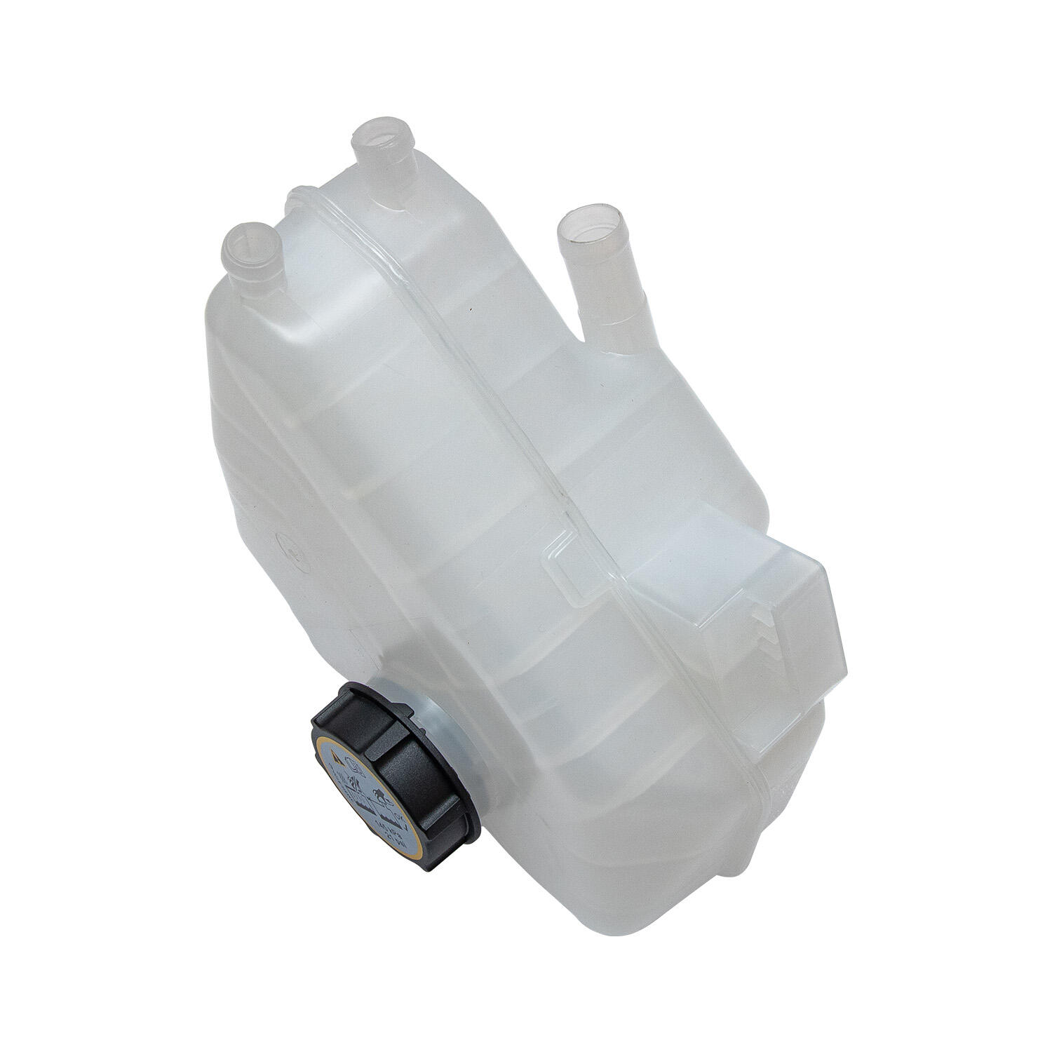
The hose connection ports on overflow tanks must be positioned to align with the existing hose routing architecture of each vehicle platform. This includes both the main overflow inlet from the radiator cap neck or coolant reservoir fill circuit, and the return port through which cooled coolant re-enters the radiator when the system cools down. The angle, height, and diameter of each port are all platform-specific parameters that directly affect how cleanly the overflow tanks integrate with the surrounding plumbing.
In some platform customization projects, the number of ports is also adjusted to suit the cooling circuit complexity of the target vehicle. Engines with separate heating circuits, turbocharger cooling loops, or auxiliary oil coolers may require additional ports on the overflow tanks to accommodate these additional circuit branches. Engineers must map the full cooling circuit topology of the target platform before finalizing port specification to ensure no circuit branches are left unaccounted for.
Correct port sizing is equally important. Undersized ports increase coolant flow resistance and can cause delayed return of coolant to the radiator after a hot shutdown, while oversized ports may generate turbulence and air entrainment within the tank body. Platform-specific port sizing is determined from OEM hose specifications and flow rate calculations based on the cooling system pump capacity of the target engine.
Sensor Integration and Level Indication Features
Modern vehicle platforms increasingly require overflow tanks to host integrated sensors for coolant level warning, temperature monitoring, or even pressure sensing. Custom overflow tanks for these platforms must incorporate precision-machined sensor boss pockets with the correct thread form, depth, and sealing surface geometry to accept OEM or compatible aftermarket sensors without modification. The sensor boss position must also ensure that the sensor element is immersed in coolant at the minimum safe level, providing accurate and timely warning of low coolant conditions.
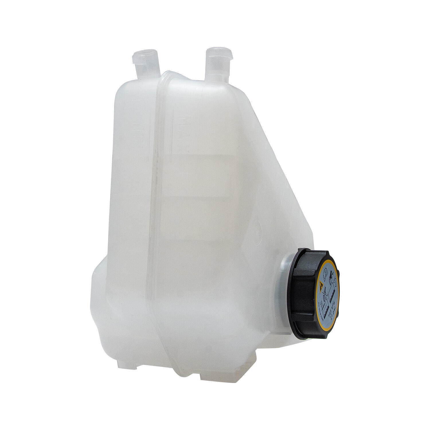
Visual level indicators are another feature that varies by platform. Some overflow tanks use a simple translucent polymer wall to allow direct visual inspection of fluid level, while others — particularly those fabricated in aluminum — incorporate a sight glass fitting, a float-and-rod indicator, or external level markings scribed into a polished panel section. The choice of level indication method is driven partly by the visibility requirements of the specific engine bay layout and partly by the preferences of the OEM or custom builder.
For platforms with electronic driver information systems, overflow tanks may also need to incorporate wiring harness routing clips or brackets to manage sensor leads and prevent chafing against hot or moving components. This level of detail reflects how deeply platform-specific the design of overflow tanks can become when properly executed for a given vehicle application.
FAQ
Why can't the same overflow tank design be used across all vehicle platforms?
Each vehicle platform has unique engine bay geometry, system pressure requirements, coolant volume, and hose routing paths. Using a universal overflow tank design would compromise sealing integrity, cause hose routing misalignment, and potentially mismatch system pressure ratings — all of which can lead to cooling system failure. Platform-specific design ensures that every dimension, port location, and material specification matches the exact operating environment of the target vehicle.
What are the main differences between aluminum and polymer overflow tanks for off-road vehicles?
Aluminum overflow tanks offer superior strength, repairability, and thermal conductivity, making them well-suited to off-road and expedition platforms where durability and field serviceability are priorities. Polymer tanks are lighter, lower in cost, and can be molded into complex shapes in a single operation, making them preferable for high-volume production vehicles. The right choice depends on the specific operating conditions, budget requirements, and service life expectations of the target platform.
How is the correct capacity determined when customizing overflow tanks for a specific engine?
Capacity is determined by calculating the total coolant volume of the engine and cooling circuit, then applying the expected thermal expansion coefficient of the coolant across the operating temperature range. A safety margin is added to accommodate extreme operating conditions. The resulting figure defines the minimum usable volume of the overflow tank, and the final tank design includes clearly marked cold and hot level indicators calibrated to this specific platform's expansion range.
Can overflow tanks be retrofitted with sensors for platforms that did not originally include them?
Yes, custom overflow tanks can be fabricated with sensor boss pockets for platforms that did not originally include coolant level or temperature sensors. This is a common upgrade for fleet operators and vehicle converters who want to add electronic monitoring capability to older or commercial vehicle platforms. The sensor boss specification must match the sensor type being installed, and the boss position must ensure accurate immersion depth at the minimum safe coolant level.
Table of Contents
- The Role of Platform-Specific Geometry in Tank Design
- Material Selection Tailored to Operating Environment
- Pressure Rating and Capacity Engineering by Platform
- Port Configuration and Hose Integration for Platform Compatibility
-
FAQ
- Why can't the same overflow tank design be used across all vehicle platforms?
- What are the main differences between aluminum and polymer overflow tanks for off-road vehicles?
- How is the correct capacity determined when customizing overflow tanks for a specific engine?
- Can overflow tanks be retrofitted with sensors for platforms that did not originally include them?